{{ keyword }}
 4. Kirchhoffs second rule (the loop rule) applies to potential differences. One way to check that the solutions are consistent is to check the power supplied by the voltage sources and the power dissipated by the resistors: \[P_{in} = I_1V_1 + I_3V_2 = 130 \, W, \nonumber\], \[P_{out} = I_1^2R_1 + I_2^2R_2 + I_3^2R_3 + I_3^2R_4 = 130 \, W. \nonumber\]. The practical observations ofOhms law experimentnever match the theoretical readings. Accessibility StatementFor more information contact us atinfo@libretexts.orgor check out our status page at https://status.libretexts.org. 1 VERIFICATION OF KIRCHHOFFS LAWS AIM: To verify Kirchhoffs current law and Kirchhoffs voltage law for the given circuit. Use voltages to determine currents through resistors via Ohms law. The circuit consists of a voltage source & the R-L-C combination in series with it. %
The voltmeter measures the potential difference between two points. 3. To solve the three equations for the three unknown currents, start by eliminating current \(I_2\). <<184d0954e2f6cf42b4cad70bb0a262a2>]>>
o#IE^(GAGXryaVDO,u) Applying the junction rule yields the following three equations. This flow would be a current, thus violating the law. ?æ I guess that would depend on what experiment you do. But what do you do then? Also, find the potential difference between points \(A\) and \(D.\), Ans: Since it is given in the question that there is no current flowing through the \(4\,\Omega \) resistor, so all the current flowing along \(FE\) will go along \(ED\) (By Kirchhoffs first law).Then, the current distribution is shown in the below circuit, Now, Applying Kirchhoffs second law in mesh \(AFEBA,\)We have:- \( 1 \times I 1 \times I 4 \times 0 6 + 9 = 0\)\(\Rightarrow \,\,\, 2I + 3 = 0\)\(\Rightarrow \,\,\,\,I = \frac{3}{2}\,\rm{A}\,\,\,\,\,\,\,\,\,\,\,\,..\left( {\rm{1}} \right)\)Again, Applying Kirchhoffs \({{\rm{2}}^{{\rm{nd}}}}\) law in mesh \(AFDCA,\)We have: \( 1 \times I 1 \times I I \times R 3 + 9 = 0\)\(\Rightarrow \,\,\, 2I IR + 6 = 0\)\( \Rightarrow 2I + IR = 6..\left( 2 \right)\)From equations \(\left( 1 \right)\) and \(\left( 2 \right),\) we get\( \Rightarrow \left( {2 \times \frac{3}{2}} \right) + \frac{3}{2}R = 6\)\( \Rightarrow R = 2\,\Omega \)Again, for potential differences across \(A\) and \(D\) along with AFD,We have:- \({V_A} \frac{3}{2} \times 1 \frac{3}{2} \times 1 = {V_D}\)\( \Rightarrow {V_A} {V_D} = 3\,\rm{V}\). Four branches are connected to this node. ARu8xx)12#SHIt$,G>S) I5H$. 0000000016 00000 n
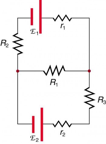
A solar-cell array or module usually consists of between 36 and 72 cells, with a power output of 50 W to 140 W. Solar cells, like batteries, provide a direct current (dc) voltage. Consider the circuit in Figure \(\PageIndex{8a}\). . When a load is placed across voltage sources in series, as in Figure \(\PageIndex{14}\), we can find the current: \[(\epsilon_1 - Ir_1) + (\epsilon_2 - Ir_2) = IR,\], \[Ir_1 + Ir_2 + IR = \epsilon_1 + \epsilon_2,\], \[I = \frac{\epsilon_1 + \epsilon_2}{r_1 + r_2 + R}.\]. This loop could have been analyzed using the previous methods, but we will demonstrate the power of Kirchhoffs method in the next section. Using Equation \ref{eq4}results in \(I_3 = -2.00 \, A\). x\s8OU3@VU\fv&W=2eiFR'_ }JH o /!^z7"<=)?KXDYqX(mXg&):x\|Qf"VA "#Dr[jAL:\_wRH|LIhh NO NAME OF THE EQUIPMENT TYPE RANGE QUANTITY 1 Resistors 100 3 2 Ammeter MC (0-200)mA 3 3 Multimeter Digital 1 4 Regulated Power Supply (RPS) DC (0-30)V 2
4. Kirchhoffs second rule (the loop rule) applies to potential differences. One way to check that the solutions are consistent is to check the power supplied by the voltage sources and the power dissipated by the resistors: \[P_{in} = I_1V_1 + I_3V_2 = 130 \, W, \nonumber\], \[P_{out} = I_1^2R_1 + I_2^2R_2 + I_3^2R_3 + I_3^2R_4 = 130 \, W. \nonumber\]. The practical observations ofOhms law experimentnever match the theoretical readings. Accessibility StatementFor more information contact us atinfo@libretexts.orgor check out our status page at https://status.libretexts.org. 1 VERIFICATION OF KIRCHHOFFS LAWS AIM: To verify Kirchhoffs current law and Kirchhoffs voltage law for the given circuit. Use voltages to determine currents through resistors via Ohms law. The circuit consists of a voltage source & the R-L-C combination in series with it. %
The voltmeter measures the potential difference between two points. 3. To solve the three equations for the three unknown currents, start by eliminating current \(I_2\). <<184d0954e2f6cf42b4cad70bb0a262a2>]>>
o#IE^(GAGXryaVDO,u) Applying the junction rule yields the following three equations. This flow would be a current, thus violating the law. ?æ I guess that would depend on what experiment you do. But what do you do then? Also, find the potential difference between points \(A\) and \(D.\), Ans: Since it is given in the question that there is no current flowing through the \(4\,\Omega \) resistor, so all the current flowing along \(FE\) will go along \(ED\) (By Kirchhoffs first law).Then, the current distribution is shown in the below circuit, Now, Applying Kirchhoffs second law in mesh \(AFEBA,\)We have:- \( 1 \times I 1 \times I 4 \times 0 6 + 9 = 0\)\(\Rightarrow \,\,\, 2I + 3 = 0\)\(\Rightarrow \,\,\,\,I = \frac{3}{2}\,\rm{A}\,\,\,\,\,\,\,\,\,\,\,\,..\left( {\rm{1}} \right)\)Again, Applying Kirchhoffs \({{\rm{2}}^{{\rm{nd}}}}\) law in mesh \(AFDCA,\)We have: \( 1 \times I 1 \times I I \times R 3 + 9 = 0\)\(\Rightarrow \,\,\, 2I IR + 6 = 0\)\( \Rightarrow 2I + IR = 6..\left( 2 \right)\)From equations \(\left( 1 \right)\) and \(\left( 2 \right),\) we get\( \Rightarrow \left( {2 \times \frac{3}{2}} \right) + \frac{3}{2}R = 6\)\( \Rightarrow R = 2\,\Omega \)Again, for potential differences across \(A\) and \(D\) along with AFD,We have:- \({V_A} \frac{3}{2} \times 1 \frac{3}{2} \times 1 = {V_D}\)\( \Rightarrow {V_A} {V_D} = 3\,\rm{V}\). Four branches are connected to this node. ARu8xx)12#SHIt$,G>S) I5H$. 0000000016 00000 n
A solar-cell array or module usually consists of between 36 and 72 cells, with a power output of 50 W to 140 W. Solar cells, like batteries, provide a direct current (dc) voltage. Consider the circuit in Figure \(\PageIndex{8a}\). . When a load is placed across voltage sources in series, as in Figure \(\PageIndex{14}\), we can find the current: \[(\epsilon_1 - Ir_1) + (\epsilon_2 - Ir_2) = IR,\], \[Ir_1 + Ir_2 + IR = \epsilon_1 + \epsilon_2,\], \[I = \frac{\epsilon_1 + \epsilon_2}{r_1 + r_2 + R}.\]. This loop could have been analyzed using the previous methods, but we will demonstrate the power of Kirchhoffs method in the next section. Using Equation \ref{eq4}results in \(I_3 = -2.00 \, A\). x\s8OU3@VU\fv&W=2eiFR'_ }JH o /!^z7"<=)?KXDYqX(mXg&):x\|Qf"VA "#Dr[jAL:\_wRH|LIhh NO NAME OF THE EQUIPMENT TYPE RANGE QUANTITY 1 Resistors 100 3 2 Ammeter MC (0-200)mA 3 3 Multimeter Digital 1 4 Regulated Power Supply (RPS) DC (0-30)V 2  Lets start off by understanding the types of errors. Kirchhoffs loop rule is a rule pertaining to circuits that is based upon the principle of conservation of energy. 3)Lab temperature being hot. Loop fcdef: \(\epsilon_2 - I_2r_2 - IR = 0,\) \(\epsilon - I_2r_2 - IR = 0.\). The second voltage source consumes power: \(P_{out} = IV_2 + I^2R_1 + I^2R_2 = 7.2 \, mW.\). 4 0 obj
Option (d) reflects more loops than necessary to solve the circuit. 0000002273 00000 n
We have three unknowns, so three equations are required. It helps in knowing the energy transfer in different parts of the circuit. Next, we cross \(R_3\) and \(R_4\) in the same direction as the current flow \(I_3\) and subtract the potential drops \(I_3R_3\) and \(I_3R_4\). Consider the Kirchhoff analysis of the circuit in Figure \(\PageIndex{15b}\). A method to quantify the error probability at the Kirchhoff-law-Johnson-noise (KLJN) secure key exchange is introduced. It connects in parallel to the circuit. Sources of errors in experiments to verify Ohms law can be as simple as temperature or pressure. &Y=tmAsrfU@`w|'`$'CY6pb'EY57-}Fd-%k -Dq5Kqs`{P
~8F*h}Eur{`kWX!nU>-G{)U*.H?W9?A'SknZ|B
@cRQ+4g `uw1wa6@').IOuAC-T%Bt%8?n8<
I5 Figure \(\PageIndex{15}\) shows two batteries with identical emfs in parallel and connected to a load resistance. Consider Loop abcda and use Figure \(\PageIndex{5}\) to write the loop equation. Note that the current is the same through resistors \(R_3\) and \(R_4\),because they are connected in series. Find the current flowing in the circuit in Figure \(\PageIndex{12}\). The number of nodes depends on the circuit. Youll also learn to obtain quite accurate readings. 0000001418 00000 n
They help in calculating the flow of current in different streams through the network. Random errors: An accidental error whose cause is unknown. xref
3. Wrong connectingthe ammeter will damage the instrument. %PDF-1.4
%
They can be wired together in series or in parallel - connected like the batteries discussed earlier. The result is Equation\ref{eq4}: \[6 \, \Omega I_1 - 3 \Omega I_3 = 24 \, V. \label{eq4}\]. For instance, an LED flashlight may have two AAA cell batteries, each with a terminal voltage of 1.5 V, to provide 3.0 V to the flashlight. The major drawback of Kirchhoffs law is that it assumes there is no fluctuating Magnetic field across the area of the loop which can cause a change in magnetic flux and generation of \({\rm{EMF}}\) in the circuit. If fingers were in contact with both leads of the multi-meter when taking resistance measurements the readings would be slightly off. Lets examine some steps in this procedure more closely. Voltage increases as we cross the battery, whereas voltage decreases as we travel across a resistor. From points d to a, nothing is done because there are no components. In this circuit, the previous methods cannot be used, because not all the resistors are in clear series or parallel configurations that can be reduced. Finally, the voltage source is crossed from the positive terminal to the negative terminal, and the voltage source \(V_2\) is subtracted. A variable power supply displays the output voltages on its main screen. If you get stuck do let us know in the comments section below and we will get back to you at the earliest. Is Brooke shields related to willow shields? Webthere are three sources of voltage in this picture. When choosing the loops in the circuit, you need enough loops so that each component is covered once, without repeating loops. Photovoltaic generation, which is the conversion of sunlight directly into electricity, is based upon the photoelectric effect. WebEXPERIMENT NO. Let us understand this with an example. 0000002519 00000 n
Also, during the application of KVL, we maintain the same anti-clockwise or clockwise direction from the point we started in the loop and account for all voltage drops as negative and rises as positive. The usefulness of these labels will become apparent soon. It may be significant that you have opposite errors of the same magnitude in two different loops. While low-quality multimeters yield wrong observations, they are equally dangerous. In this circuit, points b and e each have three wires connected, making them junctions. It is based on the law of Conservation of Energy. three percent. The result is Equation \ref{eq5}: \[3 \Omega I_1 + 7 \Omega I_3 = -5 \, V. \label{eq5}\]. From the given circuit in the below image, find the value of \(I\)? The resistors all had values in the kilo-ohm range, such large resistance values would make it difficult to exactly measure the small currents passing through them. The power supplied equals the power dissipated by the resistors. Q.4. These may be currents, voltages, or resistances. .eM HA#dv:v"~}GmQECjtF&%=%,]JY224lM?,dB9sWeI2K.QbP1 @HA*-8A:$-p6G&
(9c ET[#@ZT| )HG 4>F+fQ+~Vb-?L+v6]l \h=kQNEG//_V k/[+*6y+b. Try our app on Play store: Ohms Any number of batteries can be connected in series. The principle of conservation of energy implies that the directed sum of the The power dissipated or consumed by the circuit equals the power supplied to the circuit, but notice that the current in the battery \(V_1\) is flowing through the battery from the positive terminal to the negative terminal and consumes power. A method to check the calculations is to compute the power dissipated by the resistors and the power supplied by the voltage sources: \[P_{source} = I_1V_1 + I_2V_3 + I_3V_2 = 0.10 \, + 0.69 \, W + 0.30 \, W = 1.09 \, W.\]. The second law of Kirchhoff states that the sum of voltage drops across each electrical component connected in the loop will be equal to zero. @zeD$kR~E,9pu1MKb-E~~j`\a C&y||) a(5^9)S4;5-sd~ c>!w0,SLJBLDXB~-8AVkr//| It suggests a common source for the error. When using Kirchhoffs laws, you need to decide which loops to use and the direction of current flow through each loop. It helps in knowing the direction of current in different loops of the circuits. Under bright noon sunlight, a current per unit area of about \(100 \, mA/cm^2\) of cell surface area is produced by typical single-crystal cells. The loop is designated as Loop abcda, and the labels help keep track of the voltage differences as we travel around the circuit. Ans: Yes, Kirchhoffs laws fail at high frequency, because both the law \ ( { {\rm {KCL}}}\) and \ ( { {\rm {KVL}}}\) are not suitable for \ ( { {\rm {AC}}}\) circuits of high frequencies. Wrong connecting the voltmeter will yield wrong readings. xb```b``1``a`y @j000|b5):CS>R/$PII66V=W2GJ\e+:{P,MA3\GwgK:8520F "3::qZGG/(CjbqKtPcY,bqx#kxD7)btZ!5ChnFW0CUnl!J BA
As an example, some diesel trucks use two 12-V batteries in parallel; they produce a total emf of 12 V but can deliver the larger current needed to start a diesel engine. As expected, the internal resistances increase the equivalent resistance. WebA method to quantify the error probability at the Kirchhoff-law-Johnson-noise (KLJN) secure key exchange is introduced. For example, consider a simple loop with no junctions, as in Figure \(\PageIndex{3}\). i.e \(\sum\limits_{k = 1}^n {{I_k}} = 0\). It is a fairly common experiment Today youll learn the 5 error sources which are responsible for misleading readings. Why fibrous material has only one falling period in drying curve? In such cases, current may startcan flowing in an open circuit because in these cases, conductors or wires are acting as transmission lines. What do you mean by node and a mesh? Any number of voltage sources, including batteries, can be connected in series. 0000001559 00000 n
Legal. Every component must be contained in at least one loop, but a component may be contained in more than one loop. The voltage of the voltage source is added to the equation and the potential drop of the resistor \(R_1\) is subtracted. When the batteries are connect in parallel, the positive terminals are connected together and the negative terminals are connected together, and the load resistance is connected to the positive and negative terminals. Hn0E )$8LC4JFG#r,-wTXS1(*j2c %%EOF
The loop rule is stated in terms of potential V rather than potential energy, but the two are related since \(U = qV\). Normally, voltage sources in parallel have identical emfs. Note that according to Figure \(\PageIndex{5}\), battery \(V_1\) will be added and battery \(V_2\) will be subtracted. Now we can apply Kirchhoffs loop rule, using the map in Figure \(\PageIndex{5}\). +\epsilon_{N-1} + \epsilon_N) - I(r_1 + r_2 + . What time is 11 59 pm is it Night or Morning? When batteries are connected in parallel, they usually have equal emfs and the terminal voltage is equal to the emf minus the equivalent internal resistance times the current, where the equivalent internal resistance is smaller than the individual internal resistances. This circuit has three unknowns, so we need three linearly independent equations to analyze it. If the arrow is in the opposite direction of the conventional current flow, the result for the current in question will be negative but the answer will still be correct. Note that the solution for the current \(I_3\) is negative. Kirchhoffs loop rule states that the algebraic sum of potential differences, including voltage supplied by the voltage sources and resistive elements, in any loop must be equal to zero. Using Kirchhoffs loop rule for the circuit in part (b) gives the result, \[\epsilon_1 - Ir_1 + \epsilon_2 - Ir_2 - IR = 0,\], \[[(\epsilon_1 + \epsilon_2) - I(r_1 + r_2)] - IR = 0.\], When voltage sources are in series, their internal resistances can be added together and their emfs can be added together to get the total values. If there are as many independent equations as unknowns, then the problem can be solved. What are the names of God in various Kenyan tribes? For N batteries in parallel, the terminal voltage is equal to, \[V_{terminal} = \epsilon - I \left(\frac{1}{r_1} + \frac{1}{r_2} + . Gustav Kirchhoff provided a better understanding to solve simple as well as complex circuits and networks. How can a map enhance your understanding? The voltage drop across the resistor is taken as negative if the direction of the looping is the same as the direction of the current flowing through the circuit. Use the map in Figure \(\PageIndex{5}\). Samuel J. Ling (Truman State University),Jeff Sanny (Loyola Marymount University), and Bill Moebswith many contributing authors. <>/ProcSet[/PDF/Text/ImageB/ImageC/ImageI] >>/MediaBox[ 0 0 792 612] /Contents 4 0 R/Group<>/Tabs/S/StructParents 0>>
Simplify the equations by placing the unknowns on one side of the equations. The first loop equation can be simplified by dividing both sides by 3.00. . He finally published the law in 1827 and generalized his observations in single statement: The current flowing through the resistor is directly proportional to the voltage applied across it. This would account for part of Simplify the equations. Your multimeter is the actual tool which measures the electrical quantities. Individual solar cells are connected electrically in modules to meet electrical energy needs. 0
623 0 obj<>stream
The power supplied equals the power dissipated by the resistors and consumed by the battery \(V_1\). Any number of batteries can be connected in parallel. Choose the loops in the circuit. This page titled 10.4: Kirchhoff's Rules is shared under a CC BY 4.0 license and was authored, remixed, and/or curated by OpenStax via source content that was edited to the style and standards of the LibreTexts platform; a detailed edit history is available upon request. These laws can be applied in any circuit (with some limitations), and useful to find the unknown values in complex circuits and networks. Loop abcfa: \(\epsilon_2 - I_1r_1 + I_2r_2 - \epsilon = 0, \, I_1r_1 = I_2r_2\). %PDF-1.5
Characterize the operation of a flex sensor. endobj
Current is the flow of charge, and charge is conserved; thus, whatever charge flows into the junction must flow out. In this simple case, since the voltage sources are in parallel, the total emf is the same as the individual emfs of each battery. There is only one loop and no nodes. Using Kirchhoffs Law we have: V ~ S V ~ C V ~ R 0 (13) Figure 8 Basic RC circuit with signal generator as a voltage source Where \(n\) is the total number of all the branches at with currents flowing towards or away from the node. Sources of errors in experiments to verify Ohms law can be as This circuit can be analyzed using Kirchhoffs rules. Although it is an over-simplification, an analogy can be made with water pipes connected in a plumbing junction. Current from a dc voltage source is unidirectional. WebKirchhoff's Laws for current and voltage lie at the heart of circuit analysis. In case of Ohms law, you can commit a personal error by: The ammeter is used to measure the current. It always connects in series with the circuit. Carbon and metal film resistors are the most popular class of resistors which are employed in our labs. Look for transcription errors in your recorded measurements (or you may have transcribed digits when you initially wrote down a measurement). 621 14
Since the wires have negligible resistance, the voltage remains constant as we cross the wires connecting the components. Using Kirchhoffs method of analysis requires several steps, as listed in the following procedure. A major source of error that applies to all three cases was the measuring process. The circuit can be analyzed using Kirchhoffs loop rule. Focus on node \(A\) from a resistor network. In Figure \(\PageIndex{10}\), Loop abefa includes the voltage source \(V_1\) and resistors \(R_1\) and \(R_2\). 0000004149 00000 n
Note:- Kirchhoffs Voltage Law is based on the law of conservation of energy, because the net change in the energy of a charge, after the charge completes a closed path must be zero. Many complex circuits cannot be analyzed with the series-parallel techniques developed in the preceding sections. Locations on the diagram have been labeled with letters a through h. In the solution, we apply the junction and loop rules, seeking three independent equations to allow us to solve for the three unknown currents. The first voltage source supplies power: \(P_{in} = IV_1 = 7.20 \, mW\). WebDispute common misconceptions of the application of Kirchhoffs voltage law. How would the results change if the direction of the current was chosen to be counterclockwise, from point b to point a? (Well ignore it here). We start at point e and move to point b, crossing \(R_2\) in the opposite direction as the current flow \(I_2\). The resistors \(R_1\) and \(R_2\) are in series and can be reduced to an equivalent resistance. This circuit is sufficiently complex that the currents cannot be found using Ohms law and the series-parallel techniquesit is necessary to use Kirchhoffs rules. Because charge is conserved, the only way this is possible is if there is a flow of charge across the boundary of the region. Make sure at least one current points into the junction and at least one current points out of the junction. Label each junction with the currents and directions into and out of it. Kirchhoffs law is not suitable for high-frequency \({\rm{AC}}\) circuits. WebState whether or not the experimental results obtained verify Kirchoff's current law and Kirchoff's voltage Conclusion State any conclusions that you may draw from this experiment regarding the connection between theoretical model of :). For the time being, the accuracy of components decreases and your supply might display wrong results. There are two loops and a node at point b and \(\epsilon = \epsilon_1 = \epsilon_2\). The equation for Junction b is \(I_1 = I_2 + I_3\), and the equation for Junction e is \(I_2 + I_3 = I_1\). When applying KCL, we have to consider the currents leaving a junction to be negative and the currents entering the junction to be taken as positive in sign. experiment is the law of inertia. By the end of the section, you will be able to: We have just seen that some circuits may be analyzed by reducing a circuit to a single voltage source and an equivalent resistance. Moving from point b to point e, the resistor \(R_2\) is crossed in the same direction as the current flow \(I_2\) so the potential drop \(I_2R_2\) is subtracted. The second loop, Loop ebcde, starts at point e and includes resistors \(R_2\) and \(R_3\), and the voltage source \(V_2\). Q.2. What is the Junction and loop Rule?Ans: The junction rule is also known as Kirchhoffs Current Law KCL and it states that at any junction the sum of the entering currents is equal to the sum of the leaving currents.Kirchhoffs Loop Rule also known as Kirchhoffs Voltage Law KVL and it states that the sum of the voltage differences around the loop must be equal to zero. This is the correct answer, but suggests that the arrow originally drawn in the junction analysis is the direction opposite of conventional current flow. What is Node Voltage?Ans: When we use the term node voltage, we are referring to the potential difference between two nodes of a circuit. The algebraic sum of changes in potential around any closed circuit path (loop) must be zero: \[\sum V = 0.\], Label points in the circuit diagram using lowercase letters. By applying Kirchhoffs rules, we generate a set of linear equations that allow us to find the unknown values in circuits. 3 0 obj
The parallel connection reduces the internal resistance and thus can produce a larger current. More tolerance means your resistance, and thus the voltage/current will fluctuate away from the theoretical value. Two batteries connected in series are shown in Figure \(\PageIndex{13}\). What is the importance of Kirchhoffs law in daily life?Ans: Kirchhoffs laws can be used to determine the values of unknown values like current, voltage in the circuit. experiment. The leftmost band of carbon resistors indicates the possible tolerance of resistance. Adding seven times Equation \ref{eq4}and three times Equation \ref{eq5}results in \(51 \, \Omega I_1 = 153 \, V\), or \(I_1 = 3.00 \, A\). Currents have been labeled \(I_1, \, I_2\), and \(I_3\) in the figure, and assumptions have been made about their directions. endstream
endobj
634 0 obj<>/W[1 1 1]/Type/XRef/Index[48 573]>>stream
We now provide explanations of these two rules, followed by problem-solving hints for applying them and a worked example that uses them. Start to apply Kirchhoffs junction rule \(\left(\sum I_{in} = \sum I_{out}\right)\) by drawing arrows representing the currents and labeling each arrow, as shown in Figure \(\PageIndex{9}\). A junction, also known as a node, is a connection of three or more wires. \label{eq3}\]. In a closed loop, whatever energy is supplied by a voltage source, the energy must be transferred into other forms by the devices in the loop, since there are no other ways in which energy can be transferred into or out of the circuit. \[\text{Junction b:}\, I_1 - I_2 - I_3 = 0. If the direction of current flow is not obvious, choosing any direction is sufficient as long as at least one current points into the junction and at least one current points out of the junction. Verify Kirchhoffs laws. In analyzing the circuit in Example \(\PageIndex{2}\), the direction of current flow was chosen to be clockwise, from point a to point b. The loop equation can be used to find the current through the loop: \[I = \frac{V}{R_1 +R_2 +R_3} = \frac{12.00 \, V}{1.00 \, \Omega + 2.00 \, \Omega + 3.00 \, \Omega} = 2.00 \, A.\]. Lets take an example to understand Kirchhoffs Voltage Law. Start at point a and travel to point b. In this section, we elaborate on the use of Kirchhoffs rules to analyze more complex circuits. First, label the circuit as shown in part (b). The most interesting finding Those are the signal generator, the capacitor and the resistor. We now have three equations, which we can solve for the three unknowns. From c to d, the potential drop across \(R_3\) is subtracted. We also acknowledge previous National Science Foundation support under grant numbers 1246120, 1525057, and 1413739. Such resistors have a tolerance value which ranges between 0.05-20%. \[Loop \, abcdefa: \, I_1(R_1 + R_4) - I_2(R_2 + R_5 + R_6) = V_1 - V_3.\], \[Loop \, cdefc: \, I_2(R_2 + R_5 + R_6) + I_3R_3 = V_2 + V_3.\]. Note:- Kirchhoffs current law supports the law of conservation of charge. Note that the same current I is found in each battery because they are connected in series. In \(1845,\) he formulated two laws known as Kirchhoffs Voltage Law (KVL) and Kirchhoffs Current Law (KCL). However, you can take some precautions to closely match the values. These laws are used for the analysis of circuits. Here, \(n\) is the total number of electrical components in the loop. With these two laws, plus the equations for individual component (resistor, capacitor, inductor), we have the basic tool set we need to start analyzing circuits. There are no components between points f and a. If the wires in Figure \(\PageIndex{2}\) were replaced by water pipes, and the water was assumed to be incompressible, the volume of water flowing into the junction must equal the volume of water flowing out of the junction. Apply the junction rule. Batteries are connected in parallel to increase the current to the load. For this example, we will use the clockwise direction from point a to point b. Webnegative a current leaving it). Carefully take the readings to avoid the errors. What is the current direction in each circuit branch? Please check the points I've come up with already: 1)Using old and overused instruments to take readings. ^PC FX6qBohbR_Xiaiv?ihu/NKc{+4|B*Vr Ca\6m'UqaMte Kirchhoffs Laws help in the construction of complicated circuits containing numerous electrical components seen in everyday life. endstream
endobj
622 0 obj<>/OCGs[624 0 R]>>/PieceInfo<>>>/LastModified(D:20050916154646)/MarkInfo<>>>
endobj
624 0 obj<>/PageElement<>>>>>
endobj
625 0 obj<>/ProcSet[/PDF/Text]/ExtGState<>>>/StructParents 0>>
endobj
626 0 obj<>
endobj
627 0 obj<>
endobj
628 0 obj<>
endobj
629 0 obj<>stream
What SI unit for speed would you use if you were measuring the speed of a train? Wrong measurements usually happen due to careless handling behavior. Next, subtract Equation \ref{eq3}from Equation \ref{eq2}. Let us analyze this circuit to find the current through each resistor. Q.1. The second loop equation can be simplified by dividing both sides by 6.00. ";s:7:"keyword";s:46:"sources of error in kirchhoff's law experiment";s:5:"links";s:183:"82 Borough Road, London,
Articles S
Lets start off by understanding the types of errors. Kirchhoffs loop rule is a rule pertaining to circuits that is based upon the principle of conservation of energy. 3)Lab temperature being hot. Loop fcdef: \(\epsilon_2 - I_2r_2 - IR = 0,\) \(\epsilon - I_2r_2 - IR = 0.\). The second voltage source consumes power: \(P_{out} = IV_2 + I^2R_1 + I^2R_2 = 7.2 \, mW.\). 4 0 obj
Option (d) reflects more loops than necessary to solve the circuit. 0000002273 00000 n
We have three unknowns, so three equations are required. It helps in knowing the energy transfer in different parts of the circuit. Next, we cross \(R_3\) and \(R_4\) in the same direction as the current flow \(I_3\) and subtract the potential drops \(I_3R_3\) and \(I_3R_4\). Consider the Kirchhoff analysis of the circuit in Figure \(\PageIndex{15b}\). A method to quantify the error probability at the Kirchhoff-law-Johnson-noise (KLJN) secure key exchange is introduced. It connects in parallel to the circuit. Sources of errors in experiments to verify Ohms law can be as simple as temperature or pressure. &Y=tmAsrfU@`w|'`$'CY6pb'EY57-}Fd-%k -Dq5Kqs`{P
~8F*h}Eur{`kWX!nU>-G{)U*.H?W9?A'SknZ|B
@cRQ+4g `uw1wa6@').IOuAC-T%Bt%8?n8<
I5 Figure \(\PageIndex{15}\) shows two batteries with identical emfs in parallel and connected to a load resistance. Consider Loop abcda and use Figure \(\PageIndex{5}\) to write the loop equation. Note that the current is the same through resistors \(R_3\) and \(R_4\),because they are connected in series. Find the current flowing in the circuit in Figure \(\PageIndex{12}\). The number of nodes depends on the circuit. Youll also learn to obtain quite accurate readings. 0000001418 00000 n
They help in calculating the flow of current in different streams through the network. Random errors: An accidental error whose cause is unknown. xref
3. Wrong connectingthe ammeter will damage the instrument. %PDF-1.4
%
They can be wired together in series or in parallel - connected like the batteries discussed earlier. The result is Equation\ref{eq4}: \[6 \, \Omega I_1 - 3 \Omega I_3 = 24 \, V. \label{eq4}\]. For instance, an LED flashlight may have two AAA cell batteries, each with a terminal voltage of 1.5 V, to provide 3.0 V to the flashlight. The major drawback of Kirchhoffs law is that it assumes there is no fluctuating Magnetic field across the area of the loop which can cause a change in magnetic flux and generation of \({\rm{EMF}}\) in the circuit. If fingers were in contact with both leads of the multi-meter when taking resistance measurements the readings would be slightly off. Lets examine some steps in this procedure more closely. Voltage increases as we cross the battery, whereas voltage decreases as we travel across a resistor. From points d to a, nothing is done because there are no components. In this circuit, the previous methods cannot be used, because not all the resistors are in clear series or parallel configurations that can be reduced. Finally, the voltage source is crossed from the positive terminal to the negative terminal, and the voltage source \(V_2\) is subtracted. A variable power supply displays the output voltages on its main screen. If you get stuck do let us know in the comments section below and we will get back to you at the earliest. Is Brooke shields related to willow shields? Webthere are three sources of voltage in this picture. When choosing the loops in the circuit, you need enough loops so that each component is covered once, without repeating loops. Photovoltaic generation, which is the conversion of sunlight directly into electricity, is based upon the photoelectric effect. WebEXPERIMENT NO. Let us understand this with an example. 0000002519 00000 n
Also, during the application of KVL, we maintain the same anti-clockwise or clockwise direction from the point we started in the loop and account for all voltage drops as negative and rises as positive. The usefulness of these labels will become apparent soon. It may be significant that you have opposite errors of the same magnitude in two different loops. While low-quality multimeters yield wrong observations, they are equally dangerous. In this circuit, points b and e each have three wires connected, making them junctions. It is based on the law of Conservation of Energy. three percent. The result is Equation \ref{eq5}: \[3 \Omega I_1 + 7 \Omega I_3 = -5 \, V. \label{eq5}\]. From the given circuit in the below image, find the value of \(I\)? The resistors all had values in the kilo-ohm range, such large resistance values would make it difficult to exactly measure the small currents passing through them. The power supplied equals the power dissipated by the resistors. Q.4. These may be currents, voltages, or resistances. .eM HA#dv:v"~}GmQECjtF&%=%,]JY224lM?,dB9sWeI2K.QbP1 @HA*-8A:$-p6G&
(9c ET[#@ZT| )HG 4>F+fQ+~Vb-?L+v6]l \h=kQNEG//_V k/[+*6y+b. Try our app on Play store: Ohms Any number of batteries can be connected in series. The principle of conservation of energy implies that the directed sum of the The power dissipated or consumed by the circuit equals the power supplied to the circuit, but notice that the current in the battery \(V_1\) is flowing through the battery from the positive terminal to the negative terminal and consumes power. A method to check the calculations is to compute the power dissipated by the resistors and the power supplied by the voltage sources: \[P_{source} = I_1V_1 + I_2V_3 + I_3V_2 = 0.10 \, + 0.69 \, W + 0.30 \, W = 1.09 \, W.\]. The second law of Kirchhoff states that the sum of voltage drops across each electrical component connected in the loop will be equal to zero. @zeD$kR~E,9pu1MKb-E~~j`\a C&y||) a(5^9)S4;5-sd~ c>!w0,SLJBLDXB~-8AVkr//| It suggests a common source for the error. When using Kirchhoffs laws, you need to decide which loops to use and the direction of current flow through each loop. It helps in knowing the direction of current in different loops of the circuits. Under bright noon sunlight, a current per unit area of about \(100 \, mA/cm^2\) of cell surface area is produced by typical single-crystal cells. The loop is designated as Loop abcda, and the labels help keep track of the voltage differences as we travel around the circuit. Ans: Yes, Kirchhoffs laws fail at high frequency, because both the law \ ( { {\rm {KCL}}}\) and \ ( { {\rm {KVL}}}\) are not suitable for \ ( { {\rm {AC}}}\) circuits of high frequencies. Wrong connecting the voltmeter will yield wrong readings. xb```b``1``a`y @j000|b5):CS>R/$PII66V=W2GJ\e+:{P,MA3\GwgK:8520F "3::qZGG/(CjbqKtPcY,bqx#kxD7)btZ!5ChnFW0CUnl!J BA
As an example, some diesel trucks use two 12-V batteries in parallel; they produce a total emf of 12 V but can deliver the larger current needed to start a diesel engine. As expected, the internal resistances increase the equivalent resistance. WebA method to quantify the error probability at the Kirchhoff-law-Johnson-noise (KLJN) secure key exchange is introduced. For example, consider a simple loop with no junctions, as in Figure \(\PageIndex{3}\). i.e \(\sum\limits_{k = 1}^n {{I_k}} = 0\). It is a fairly common experiment Today youll learn the 5 error sources which are responsible for misleading readings. Why fibrous material has only one falling period in drying curve? In such cases, current may startcan flowing in an open circuit because in these cases, conductors or wires are acting as transmission lines. What do you mean by node and a mesh? Any number of voltage sources, including batteries, can be connected in series. 0000001559 00000 n
Legal. Every component must be contained in at least one loop, but a component may be contained in more than one loop. The voltage of the voltage source is added to the equation and the potential drop of the resistor \(R_1\) is subtracted. When the batteries are connect in parallel, the positive terminals are connected together and the negative terminals are connected together, and the load resistance is connected to the positive and negative terminals. Hn0E )$8LC4JFG#r,-wTXS1(*j2c %%EOF
The loop rule is stated in terms of potential V rather than potential energy, but the two are related since \(U = qV\). Normally, voltage sources in parallel have identical emfs. Note that according to Figure \(\PageIndex{5}\), battery \(V_1\) will be added and battery \(V_2\) will be subtracted. Now we can apply Kirchhoffs loop rule, using the map in Figure \(\PageIndex{5}\). +\epsilon_{N-1} + \epsilon_N) - I(r_1 + r_2 + . What time is 11 59 pm is it Night or Morning? When batteries are connected in parallel, they usually have equal emfs and the terminal voltage is equal to the emf minus the equivalent internal resistance times the current, where the equivalent internal resistance is smaller than the individual internal resistances. This circuit has three unknowns, so we need three linearly independent equations to analyze it. If the arrow is in the opposite direction of the conventional current flow, the result for the current in question will be negative but the answer will still be correct. Note that the solution for the current \(I_3\) is negative. Kirchhoffs loop rule states that the algebraic sum of potential differences, including voltage supplied by the voltage sources and resistive elements, in any loop must be equal to zero. Using Kirchhoffs loop rule for the circuit in part (b) gives the result, \[\epsilon_1 - Ir_1 + \epsilon_2 - Ir_2 - IR = 0,\], \[[(\epsilon_1 + \epsilon_2) - I(r_1 + r_2)] - IR = 0.\], When voltage sources are in series, their internal resistances can be added together and their emfs can be added together to get the total values. If there are as many independent equations as unknowns, then the problem can be solved. What are the names of God in various Kenyan tribes? For N batteries in parallel, the terminal voltage is equal to, \[V_{terminal} = \epsilon - I \left(\frac{1}{r_1} + \frac{1}{r_2} + . Gustav Kirchhoff provided a better understanding to solve simple as well as complex circuits and networks. How can a map enhance your understanding? The voltage drop across the resistor is taken as negative if the direction of the looping is the same as the direction of the current flowing through the circuit. Use the map in Figure \(\PageIndex{5}\). Samuel J. Ling (Truman State University),Jeff Sanny (Loyola Marymount University), and Bill Moebswith many contributing authors. <>/ProcSet[/PDF/Text/ImageB/ImageC/ImageI] >>/MediaBox[ 0 0 792 612] /Contents 4 0 R/Group<>/Tabs/S/StructParents 0>>
Simplify the equations by placing the unknowns on one side of the equations. The first loop equation can be simplified by dividing both sides by 3.00. . He finally published the law in 1827 and generalized his observations in single statement: The current flowing through the resistor is directly proportional to the voltage applied across it. This would account for part of Simplify the equations. Your multimeter is the actual tool which measures the electrical quantities. Individual solar cells are connected electrically in modules to meet electrical energy needs. 0
623 0 obj<>stream
The power supplied equals the power dissipated by the resistors and consumed by the battery \(V_1\). Any number of batteries can be connected in parallel. Choose the loops in the circuit. This page titled 10.4: Kirchhoff's Rules is shared under a CC BY 4.0 license and was authored, remixed, and/or curated by OpenStax via source content that was edited to the style and standards of the LibreTexts platform; a detailed edit history is available upon request. These laws can be applied in any circuit (with some limitations), and useful to find the unknown values in complex circuits and networks. Loop abcfa: \(\epsilon_2 - I_1r_1 + I_2r_2 - \epsilon = 0, \, I_1r_1 = I_2r_2\). %PDF-1.5
Characterize the operation of a flex sensor. endobj
Current is the flow of charge, and charge is conserved; thus, whatever charge flows into the junction must flow out. In this simple case, since the voltage sources are in parallel, the total emf is the same as the individual emfs of each battery. There is only one loop and no nodes. Using Kirchhoffs Law we have: V ~ S V ~ C V ~ R 0 (13) Figure 8 Basic RC circuit with signal generator as a voltage source Where \(n\) is the total number of all the branches at with currents flowing towards or away from the node. Sources of errors in experiments to verify Ohms law can be as This circuit can be analyzed using Kirchhoffs rules. Although it is an over-simplification, an analogy can be made with water pipes connected in a plumbing junction. Current from a dc voltage source is unidirectional. WebKirchhoff's Laws for current and voltage lie at the heart of circuit analysis. In case of Ohms law, you can commit a personal error by: The ammeter is used to measure the current. It always connects in series with the circuit. Carbon and metal film resistors are the most popular class of resistors which are employed in our labs. Look for transcription errors in your recorded measurements (or you may have transcribed digits when you initially wrote down a measurement). 621 14
Since the wires have negligible resistance, the voltage remains constant as we cross the wires connecting the components. Using Kirchhoffs method of analysis requires several steps, as listed in the following procedure. A major source of error that applies to all three cases was the measuring process. The circuit can be analyzed using Kirchhoffs loop rule. Focus on node \(A\) from a resistor network. In Figure \(\PageIndex{10}\), Loop abefa includes the voltage source \(V_1\) and resistors \(R_1\) and \(R_2\). 0000004149 00000 n
Note:- Kirchhoffs Voltage Law is based on the law of conservation of energy, because the net change in the energy of a charge, after the charge completes a closed path must be zero. Many complex circuits cannot be analyzed with the series-parallel techniques developed in the preceding sections. Locations on the diagram have been labeled with letters a through h. In the solution, we apply the junction and loop rules, seeking three independent equations to allow us to solve for the three unknown currents. The first voltage source supplies power: \(P_{in} = IV_1 = 7.20 \, mW\). WebDispute common misconceptions of the application of Kirchhoffs voltage law. How would the results change if the direction of the current was chosen to be counterclockwise, from point b to point a? (Well ignore it here). We start at point e and move to point b, crossing \(R_2\) in the opposite direction as the current flow \(I_2\). The resistors \(R_1\) and \(R_2\) are in series and can be reduced to an equivalent resistance. This circuit is sufficiently complex that the currents cannot be found using Ohms law and the series-parallel techniquesit is necessary to use Kirchhoffs rules. Because charge is conserved, the only way this is possible is if there is a flow of charge across the boundary of the region. Make sure at least one current points into the junction and at least one current points out of the junction. Label each junction with the currents and directions into and out of it. Kirchhoffs law is not suitable for high-frequency \({\rm{AC}}\) circuits. WebState whether or not the experimental results obtained verify Kirchoff's current law and Kirchoff's voltage Conclusion State any conclusions that you may draw from this experiment regarding the connection between theoretical model of :). For the time being, the accuracy of components decreases and your supply might display wrong results. There are two loops and a node at point b and \(\epsilon = \epsilon_1 = \epsilon_2\). The equation for Junction b is \(I_1 = I_2 + I_3\), and the equation for Junction e is \(I_2 + I_3 = I_1\). When applying KCL, we have to consider the currents leaving a junction to be negative and the currents entering the junction to be taken as positive in sign. experiment is the law of inertia. By the end of the section, you will be able to: We have just seen that some circuits may be analyzed by reducing a circuit to a single voltage source and an equivalent resistance. Moving from point b to point e, the resistor \(R_2\) is crossed in the same direction as the current flow \(I_2\) so the potential drop \(I_2R_2\) is subtracted. The second loop, Loop ebcde, starts at point e and includes resistors \(R_2\) and \(R_3\), and the voltage source \(V_2\). Q.2. What is the Junction and loop Rule?Ans: The junction rule is also known as Kirchhoffs Current Law KCL and it states that at any junction the sum of the entering currents is equal to the sum of the leaving currents.Kirchhoffs Loop Rule also known as Kirchhoffs Voltage Law KVL and it states that the sum of the voltage differences around the loop must be equal to zero. This is the correct answer, but suggests that the arrow originally drawn in the junction analysis is the direction opposite of conventional current flow. What is Node Voltage?Ans: When we use the term node voltage, we are referring to the potential difference between two nodes of a circuit. The algebraic sum of changes in potential around any closed circuit path (loop) must be zero: \[\sum V = 0.\], Label points in the circuit diagram using lowercase letters. By applying Kirchhoffs rules, we generate a set of linear equations that allow us to find the unknown values in circuits. 3 0 obj
The parallel connection reduces the internal resistance and thus can produce a larger current. More tolerance means your resistance, and thus the voltage/current will fluctuate away from the theoretical value. Two batteries connected in series are shown in Figure \(\PageIndex{13}\). What is the importance of Kirchhoffs law in daily life?Ans: Kirchhoffs laws can be used to determine the values of unknown values like current, voltage in the circuit. experiment. The leftmost band of carbon resistors indicates the possible tolerance of resistance. Adding seven times Equation \ref{eq4}and three times Equation \ref{eq5}results in \(51 \, \Omega I_1 = 153 \, V\), or \(I_1 = 3.00 \, A\). Currents have been labeled \(I_1, \, I_2\), and \(I_3\) in the figure, and assumptions have been made about their directions. endstream
endobj
634 0 obj<>/W[1 1 1]/Type/XRef/Index[48 573]>>stream
We now provide explanations of these two rules, followed by problem-solving hints for applying them and a worked example that uses them. Start to apply Kirchhoffs junction rule \(\left(\sum I_{in} = \sum I_{out}\right)\) by drawing arrows representing the currents and labeling each arrow, as shown in Figure \(\PageIndex{9}\). A junction, also known as a node, is a connection of three or more wires. \label{eq3}\]. In a closed loop, whatever energy is supplied by a voltage source, the energy must be transferred into other forms by the devices in the loop, since there are no other ways in which energy can be transferred into or out of the circuit. \[\text{Junction b:}\, I_1 - I_2 - I_3 = 0. If the direction of current flow is not obvious, choosing any direction is sufficient as long as at least one current points into the junction and at least one current points out of the junction. Verify Kirchhoffs laws. In analyzing the circuit in Example \(\PageIndex{2}\), the direction of current flow was chosen to be clockwise, from point a to point b. The loop equation can be used to find the current through the loop: \[I = \frac{V}{R_1 +R_2 +R_3} = \frac{12.00 \, V}{1.00 \, \Omega + 2.00 \, \Omega + 3.00 \, \Omega} = 2.00 \, A.\]. Lets take an example to understand Kirchhoffs Voltage Law. Start at point a and travel to point b. In this section, we elaborate on the use of Kirchhoffs rules to analyze more complex circuits. First, label the circuit as shown in part (b). The most interesting finding Those are the signal generator, the capacitor and the resistor. We now have three equations, which we can solve for the three unknowns. From c to d, the potential drop across \(R_3\) is subtracted. We also acknowledge previous National Science Foundation support under grant numbers 1246120, 1525057, and 1413739. Such resistors have a tolerance value which ranges between 0.05-20%. \[Loop \, abcdefa: \, I_1(R_1 + R_4) - I_2(R_2 + R_5 + R_6) = V_1 - V_3.\], \[Loop \, cdefc: \, I_2(R_2 + R_5 + R_6) + I_3R_3 = V_2 + V_3.\]. Note:- Kirchhoffs current law supports the law of conservation of charge. Note that the same current I is found in each battery because they are connected in series. In \(1845,\) he formulated two laws known as Kirchhoffs Voltage Law (KVL) and Kirchhoffs Current Law (KCL). However, you can take some precautions to closely match the values. These laws are used for the analysis of circuits. Here, \(n\) is the total number of electrical components in the loop. With these two laws, plus the equations for individual component (resistor, capacitor, inductor), we have the basic tool set we need to start analyzing circuits. There are no components between points f and a. If the wires in Figure \(\PageIndex{2}\) were replaced by water pipes, and the water was assumed to be incompressible, the volume of water flowing into the junction must equal the volume of water flowing out of the junction. Apply the junction rule. Batteries are connected in parallel to increase the current to the load. For this example, we will use the clockwise direction from point a to point b. Webnegative a current leaving it). Carefully take the readings to avoid the errors. What is the current direction in each circuit branch? Please check the points I've come up with already: 1)Using old and overused instruments to take readings. ^PC FX6qBohbR_Xiaiv?ihu/NKc{+4|B*Vr Ca\6m'UqaMte Kirchhoffs Laws help in the construction of complicated circuits containing numerous electrical components seen in everyday life. endstream
endobj
622 0 obj<>/OCGs[624 0 R]>>/PieceInfo<>>>/LastModified(D:20050916154646)/MarkInfo<>>>
endobj
624 0 obj<>/PageElement<>>>>>
endobj
625 0 obj<>/ProcSet[/PDF/Text]/ExtGState<>>>/StructParents 0>>
endobj
626 0 obj<>
endobj
627 0 obj<>
endobj
628 0 obj<>
endobj
629 0 obj<>stream
What SI unit for speed would you use if you were measuring the speed of a train? Wrong measurements usually happen due to careless handling behavior. Next, subtract Equation \ref{eq3}from Equation \ref{eq2}. Let us analyze this circuit to find the current through each resistor. Q.1. The second loop equation can be simplified by dividing both sides by 6.00. ";s:7:"keyword";s:46:"sources of error in kirchhoff's law experiment";s:5:"links";s:183:"82 Borough Road, London,
Articles S